Line scan mode with one click
Quickly switch to camera configurations such as line scan or long exposure
Benefit from the new "User Set Control" starting with IDS Vision Firmware 1.7 by saving and reloading optimally configured camera settings very easily. Access complete camera parameter sets from the camera memory with just one click. With manufacturer "presets", you also benefit from new camera modes such as line scan and long exposure and thus cover a much wider range of applications with your area scan camera.
Background
Industrial cameras offer many useful operating modes that can be optimally configured for any application by numerous parameters. Once you have found the "optimal" setting, it makes sense to save the configuration. Depending on the application, a camera is operated with different settings or switched between several modes. When switching, parameters no longer have to be re-entered step-by-step, but are available with just a button click. The Techtipp explains the functional enhancements of the new Vision Firmware update and the user set possibilities for your application.
Using User Sets
In two customizable "user sets" you can save complete camera settings and retrieve them at a later time. Because you save the standard and model-related function parameters of an IDS camera, these "user sets" are only compatible with this camera and are therefore stored directly in the persistent camera memory and not in a file. In addition, the firmware provides a fixed "default" setting" for continuous image capture that is compatible with most applications. This preset is also ideal as starting point for your specific user sets.
The user set control is explained using the parameter tree of the IDS Vision Cockpit. These settings can of course be applied in any other GenICam compatible application.
To display all relevant user set control parameters in the IDS Vision Cockpit tree view dialog, enter the following regular expression in the search field: "UserSet|SensorOperationMode".
Select the view scheme "Expert" and change the search field option ![]() to "Regular expressions".
to "Regular expressions".

Before you load, edit or save camera parameters via user sets, first select the desired set via the "User Set Selector" node. Loading and saving user sets is only feasible with stopped image acquisition!

Save configuration
Select "UserSet0" or "UserSet1" and execute "User Set Save" to save all currently set parameters in one of the sets.
Not saved are "DeviceUserID" and the settings of the categories "GigEVision" and "LUTControl"! The Default, Linescan and LongExposure nodes are non-writable presets from the manufacturer and can only be loaded.
Load configuration
You can load all user sets available for your model. Choose the appropriate selector and execute "User Set Load". The Linescan and LongExposure sets also change the camera's operating mode. The active camera operating mode can be queried at any time via the SensorOperationMode node. But this parameter is not writable!
Define the default set
The "User Set Default" node is used to define the default setting that will be loaded when the camera starts. Thus, you can start a camera without software intervention directly in a saved line scan configuration.
Customer-specific user sets 1 and 2 can only be selected if parameter configurations have been saved previously.
Line scan mode
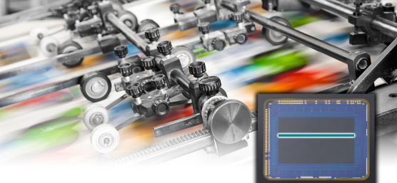
Through the "line scan mode", an IDS Vision area scan camera is also suitable for a multitude of simple applications in web inspection, for example of textiles, paper, rims or silicon wafers. Simple setup and small system costs provide a cost-effective alternative to an original line scan camera. The biggest advantage of an area scan camera with line scan mode is an easy setup of the desired image scene in basic area scan mode and the possibility to re-adjust it at later time.

The line scan preset optimizes the camera settings to capture a single sensor line in the center of the image (configurable) to continuously scan moving objects at a high line-frequency. With a color sensor, 2 lines are captured for calculating the color information. The active lines are combined to a complete image before being transferred to the PC. The Width and Height can also be adjusted via parameters.
To display all relevant image geometry parameters in the tree view of the IDS Vision Cockpit, use the following regular expression: ^Width|^Height|^Offset X$|^Offset Y$|Sensor Height
The image geometry can also be adjusted very comfortably via the "Camera Settings" dialog of the IDS Vision Cockpit:

Once you have defined the active line position and the image geometry, use the image and line triggers to adjust the acquisition time and speed to the object movement of your application. The line scan mode allows using encoders to start the acquisition of the active line at regular intervals with a line trigger, even at varying object speeds. This avoids distorted images of scanned objects.
Typical applications
Application |
Description |
Frame Trigger |
Line Trigger |
|---|---|---|---|
Printed web material |
Frames can be triggered, for example, by a light barrier. The line signal is controlled by an encoder. |
Hardware Trigger (Line0) |
Hardware Trigger |
Non-printed web material |
There is no frame sync signal. The line signal is controlled by an encoder. |
Freerun |
Hardware Trigger |
Printed web material without speed fluctuations |
Frames can be triggered, for example, by a light barrier. There is no signal that triggers a line. The starting and braking behavior of the web cannot be compensated. |
Hardware Trigger (Line0) |
Freerun |
Unprinted web material without speed fluctuations |
There is neither a frame sync signal nor a signal that triggers the lines. The starting and braking behavior of the web cannot be compensated. |
Freerun |
Freerun |
The GPIO (General Purpose Input Output) camera inputs "Line 2 and Line 3" are better suited for line triggering than the optical isolated Line 1 input. Although the external circuitry is not electrically isolated, the inputs have a faster response, which is an advantage when using high line frequencies.
Parameter example
The parameter settings for the typical application "printed web material" could have the following appearance:
UserSetSelector 		= Linescan
Execute >> UserSetLoad
OffsetY         		= 700
Height				= 2000
Width				= 1600
OffsetX				= 240
TriggerSelector 		= Framestart
	TriggerSource 		= Line0
	TriggerActiviation 	= RisingEdge
	TriggerMode 		= On
TriggerSelector 		= LineStart
	TriggerSource 		= Line2
	TriggerActiviation 	= RisingEdge
	TriggerMode 		= On
Execute >> AcquisitionStart
The Linescan preset will be loaded with the UserSetLoad command. The AcquisitionStart command turns the system into ready state to receive trigger signals. A light barrier can start image acquisition, as external trigger source on "Line0". The exposure of the active sensor line (700) is started synchronously to the web speed via "Line2", controlled by a web encoder.
Further applications and trigger possibilities with the use of counters, timers or PWM (pulse width modulation) can be found in our tech tip "Triggering according to the Lego principle".

Long exposure
With a preset it is also very easy to setup a long exposure. The "LongExposure" mode prepares the camera parameters for image acquisitions with exposure times over one second. Long exposure is recommended for all applications with image acquisition in low light conditions. Due to the longer exposure time it is not necessary to increase the gain. This also avoids strong image noise.
The preset "LongExposure" shifts the available exposure time for your recordings to a range between 1 second and a model-dependent maximum of several seconds. Apart from that, you can work in this operating mode with the same parameters as in the "Default" mode.

Summary
With the camera "user sets", you no longer have to deal with saving and restoring the camera configurations in your application yourself. Switch your camera comfortably between optimally set operating modes with a single click.
With additional presets for long exposure and line scan mode, IDS Vision cameras now cover a much wider range of applications. Many line scan applications do not require the line frequencies of a highly specialized high-speed line scan camera. These can now be realized very comfortable with IDS industrial cameras by the combination of area and line scan mode without the need for a second camera.
Further information and the download of the new IDS vision firmware can be found on our download pages.

Dipl.-Ing. Heiko Seitz is working at IDS since 2001. After years as a developer in the field of camera software, he now supports technological communication at IDS as Product Marketing Manager. With his experience, he bridges the gap between complex technology and practical knowledge transfer – for example in technical articles, webinars, or lectures.
Vision Channel
Videos and live sessions about machine vision.
Your project
How can we support you in your project? Together we will find the right solution for you!
Newsletter
Stay up to date and subscribe to our newsletter.