

Setting up Nion 3D camera in IDS peak Cockpit
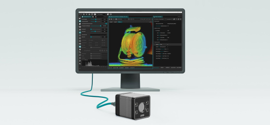
Nion getting started
1. Introduction
This guide is designed to provide information on setting up the Nion 3D ToF camera in IDS peak Cockpit and covers the operating modes, data optimisation and workspace calibration.
For instructions on installing the camera and setting it up on the network, please refer to the Nion camera manual.
2. Configuration of working range and operating modes
2.1 Working range setup
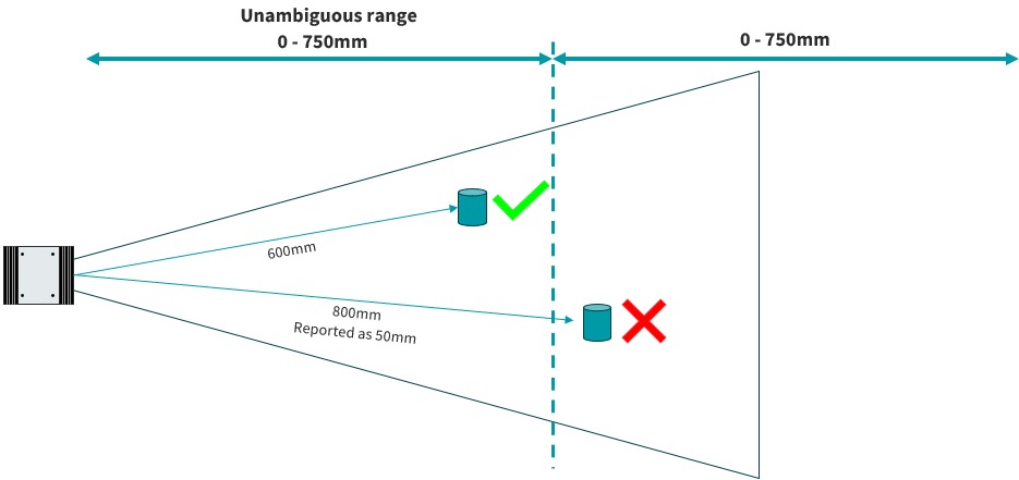
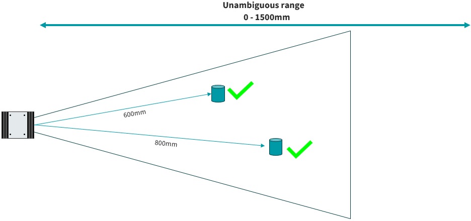
In order to optimise the accuracy of the depth data, different operating modes (or unambiguous ranges) are used.
2.2 Selecting the best mode for your application
Use the operation modes and precision tables on the Nion datasheet to determine the optimum configuration for the application considering the following:
- Unambiguous range must exceed the distance to the furthest object or surface
- Maximum exposure time - use Quad VGA operating modes to minimise motion artefacts for fast moving objects
- Spatial resolution – operating modes with Quad VGA suffix offer a higher spatial resolution
- Accuracy
- Precision
2.3 Configure operating mode
- To configure the operating mode in peak Cockpit use:

- Select the required operating mode in the drop-down menu:

- Here it is possible to save any settings to the camera UserSets area or to a *.cset file and to set the default startup parameters
3. Data optimisation
3.1 Optimise intensity image
To optimise the 3D data, use the intensity image controls (exposure and analog gain) to maximise the image brightness whilst avoiding (or minimising) saturation.
- To set up the intensity image use:

- Adjust exposure and analog gain:


- Use the histogram display to optimise image brightness
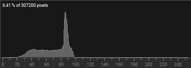
- Digital gain can be used to increase image brightness without affecting the 3D data, here some saturation is tolerable
- Gamma correction can also be applied to stretch the dynamic range of the displayed intensity image and does not affect the 3D data.
- To adjust the Gamma use:


- Once the Intensity image is correctly configured, it is a good idea to disable this component to reduce bandwidth usage
3.2 Enable and use the confidence map
The confidence map is a useful tool for further data optimisation and shows, by colour, the confidence of each point in the image. By default, this component is disabled to minimise bandwidth usage.
- To enable the confidence map use:
- Select confidence from the Image component list.

- Enable the output with the toggle switch (stop the camera acquisition if the toggle switch is not active)
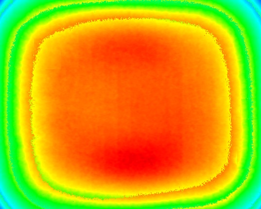

- Use the exposure and analog gain controls to adjust the confidence map to optimise the data
3.3 Nion specific parameters
There are additional parameters available to optimise the 3D data:
Noise filter |
Smoothing filter to fill gaps in 3D data and reduce noisy points |
Confidence threshold |
Filters out lower confidence points in the depth image |
Flying pixel threshold |
Filters out points “flying” between two planes in the depth image |
- To adjust these parameters, use:

- Set visibility to expert or guru

- Enter “Scan 3D” in the search bar to filter down to the relevant parameters
- Click on the required parameter and use the slider bar or text entry fields to set the parameter as required using the data displays for feedback.
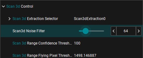
- A new custom dialog for these parameters can be created using the select parameters and apply parameter selection buttons.

4. 3D data representation
4.1 3D colour mapping
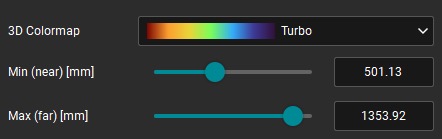
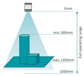
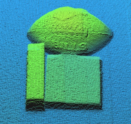
The 3D colour map is used to help visualise the 3D data by relating colour to distance or height. Using the min and max values the colour map can be adjusted to map to just the range of interest in the depth map and increase contrast in the data.
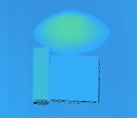
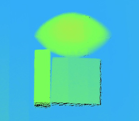
- To adjust these parameters use

- Set desired 3D colour map
- Set min (near) [mm] value to point of interest closest to the camera
- Set max (far) [mm] value to point that incorporates all points of interest in the operating range
4.2 3D data threshold
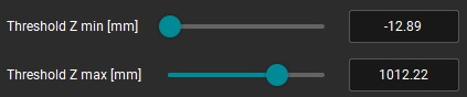
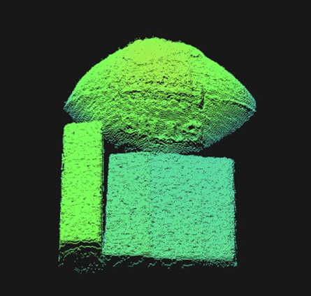
3D data can also be filtered out of the point cloud to reduce the number of points for processing. For example, if the application does not require the background for processing, this can be removed.
- To adjust these parameters, use:
- Set threshold Z min [mm] and threshold Z max [mm] as per the min and max colormap settings
5. Workspace calibration
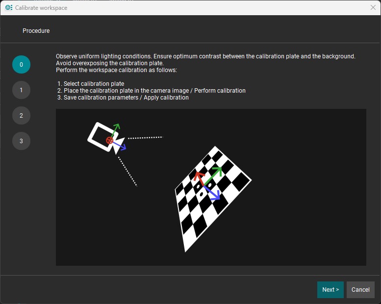
To transform the coordinates to a different reference plane, the workspace calibration wizard can be used.


- To change the 3D coordinates use:

- Follow the steps in the wizard to complete the coordinate transformation.
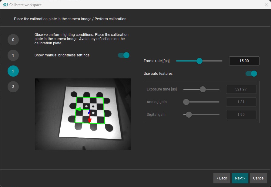
- Workspace calibration settings can be saved to or loaded from file for later use
- For additional configuration information, please refer to the Nion user manual.
- Watch the video: How-to setup and use 3D Vision with Nion - Hands On!
- For support, please contact our machine vision consulting team (login required).

Rob Webb has been at the forefront of machine vision and imaging for over 25 years, bringing deep expertise across camera technology, lighting, optics, and image processing. Since joining IDS in 2018, he has combined his technical background with commercial insight to help customers navigate an increasingly complex technology landscape. Rob is passionate about translating advanced capabilities into practical, value-driven solutions. He works closely with customers and colleagues alike to understand challenges, identify opportunities, and deliver clear, effective outcomes.
Vision Channel
Videos and live sessions about machine vision.
Your project
How can we support you in your project? Together we will find the right solution for you!
Newsletter
Stay up to date and subscribe to our newsletter.