Bandwidth under control
GigE Vision cameras transmit image data in small packets over the network, even before a captured sensor image is read out completely. This minimizes the delay of the image transfer. However, if too much data is transferred at the same time, the maximum bandwidth of a GigE network can be exceeded very quickly.
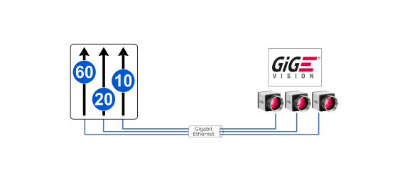
Especially multi-camera applications are affected. This results in transmission losses and increased transmission times if data has to be requested repeatedly. The GigE Vision Standard allows the configuration of transmission parameters to avoid such situations. Easily manage the available bandwidth with the extended settings of IDS GigE Vision firmware 1.3.
Background
GigE Vision camera data is transmitted as a sequence of packets. In addition to the payload data, a package also consists of header and checksum data. Depending on the MTU (Maximum Transmission Unit) setting, the amount of user data and thus the packet size (keyword: jumbo frames) can vary. There is an adjustable delay between two packages: The „Inter-packet delay“.If data packets are incorrectly transferred, the transport layer (GenTL) can request missing data packets again using a re-send mechanism. The possibility for data re-requests depends on the used transport layer. These three components together determine the complete transmission time of a camera image.

To relieve the network load in multi-camera operation or to relieve a processing system, it is necessary to reduce the network bandwidth of the transmitting devices. Inter-packet delays in the GigE Vision standard prevent bandwidth bottlenecks through transmission pauses. The packet delays cause the total transmission time to increase, since the image data is sent slower than before and thus reduces the data throughput! An increasing transmission time also results in a reduction of the maximum frame rate (Acquisition Framerate Limit).

The GigE Vision Inter-packet delay allows the data throughput of each camera to be set separately. A suitable delay in data transfer will prevent the camera from "overrunning" the transfer interface limit.
This TechTip only describes the possibilities of bandwidth management of the IDS GigE Vision firmware. Settings and monitoring of the data stream depend on the transport layer (GenTL) used.
Standard settings
The GenICam SFNC (Standard Feature Naming Convention) already defines two standard features for controlling data throughput.
- GevSCPD
- DeviceLinkThroughputLimit
The Inter-packet delay (see GevSCPD - Stream Channel Packet Delay) can be used to set a delay (in ticks of the GigE Vision timestamp counter) between two packets on the StreamChannel. This increases the transmission time of the data and reduces the bandwidth. Choosing a suitable delay between the packets is not very straightforward and to control the amount of data, this method is not very easy to use.
The DeviceLinkThroughputLimit limits the maximum bandwidth of data sent from a device. The maximum value can be specified in bytes per second. A corresponding delay between the stream channel packets is calculated, which is then used as the GevSCPD value. The unit in bytes per second allows a quite precise and intuitive control of the data throughput.
IDS extensions increase clarity
IDS implements two additional features in the GigE Vision firmware (version 1.3 and higher) that provide even more overview in bandwidth management.
- DeviceLinkCalculatedThroughput
- DeviceLinkAcquisitionFrameRateLimit
By entering a throughput limit (DeviceLinkThroughputLimit), the camera firmware calculates the required packet delays (GevSCPD) and the maximum possible frame rate (DeviceLinkAcquisitionFrameRateRateLimit), which can be reached with the current limit.
In addition, the calculated throughput (DeviceLinkCalculatedThroughput) provides information about the theoretic bandwidth of the device, which would be used without the restriction. This eliminates time-consuming calculations for each camera.

The additional features are available in every GigE Vision compatible camera application. We demonstrate them using the IDS Vision Cockpit.
Limit data throughput
If you want to use a high data bandwidth over a Gigabit Ethernet port in your GigE Vision application, you should take a look at these new IDS camera features, as bottlenecks can already occur when opening two cameras with the default settings.
Start the connected cameras without "immediate" image capture and adjust your camera settings first.
Before starting the image capture, check the calculated data throughput, the maximum possible frame rate and set a bandwidth limit if necessary. For a useful overview, filter the "Device Nodes" using the term "devicelink" and at least "Expert" user level. The following filtered device node overview shows you the parameters with sample camera bandwidth values:
By default, the cameras operate with unlimited data throughput and use the maximum adjustable throughput limit (DeviceLinkThroughputLimit) of 120 MBps. The camera in this example would generate a data throughput (DeviceLinkCalculatedThroughput) of approx. 61 MBps with current settings at a frame rate of 25 fps. Unlimited, the camera could capture and transmit up to 46 frames per second (DeviceLinkAcquisition-FrameRateLimit). Changing the camera parameters results in a change of the "calculated throughput" (De-viceLinkCalculatedThroughput) and the "maximum frame rate" (DeviceLinkAcquisitionFrameRateLimit).

However, if you limit the data throughput using "DeviceLinkThroughputLimit", regardless of the camera settings and the resulting data rate, the camera will never exceed this value.

If the throughput limit is reduced to 50 MBps in this example, a maximum frame rate of approx. 20 fps is possible with identical settings.
Since the calculated data throughput continues to exceed the limit at approx. 60 MBps, the camera can no longer transmit the frame rate of 25 fps. A data overflow occurs in the transfer buffers in the camera. If images taken cannot be buffered temporarily, the camera "drops" the images. The actual transmission rate equals the calculated maximum frame rate (21 fps).
The higher the calculated data throughput is above the specified throughput limit, the more images are discarded internally by the camera and thus not transmitted.

As a result of the bandwidth limitation, the image transmission of the camera is delayed using the data packet gaps (GevSCPD)!
Advantages of the bandwidth limitation
Distribute the available bandwidth of a Gigabit Ethernet port (120 MBps) to the connected cameras by setting appropriate bandwidth limits. This protects you from transmission bottlenecks, which can lead to erroneous and incomplete images.
You can also prioritize cameras differently by providing the cameras with different throughput limits.

System optimization
Even if you consider the GigE bandwidth limit when setting the data throughput of your cameras, high network traffic or other system-based fluctuations can cause temporary bottlenecks on the Gigabit line. As a result, incomplete images or other transmission errors may still occur.
GenTL-Settings
Depending on the GenTL used, you have different options for setting and monitoring to optimize the data transfer. Some sample features of the IDS GenTL are listed below:
- The "Stream Monitor" shows via the "Buffer Fill Level" how much percent of the transmission buffer is correctly transmitted. And the "Resend Request Count" shows the usage of the buffer re-requests.
- You can use "Loss Handling" to control how much data is to be re-requested. This feature is disabled by default.
- "Incomplete" images are counted by the IDS GenTL but still transmitted. The user can then decide for himself whether he wants to use this image data.
Provide reserves
In order to avoid transmission errors in case of temporary performance fluctuations in the network, you should provide reserves in any case. When distributing the available bandwidth, plan about 10% reserve that is not used by the cameras.
Notes on setting the network card used
- We recommend setting the Receive Descriptors to the maximum value in the settings of the network card.
- It is also recommended to adjust Jumbo Frames (also: Jumbo Packet, Large Packet, Large Frame) to the maximum value in the settings of the network card.
Note that the connection between the camera and the PC must be jumbo-capable all the way through to ensure the transmission of the jumbo packets. For information about these settings, refer to the network card manufacturer's description.
Summary
In addition to the bandwidth management features already defined in the standard, two additional IDS parameters have been implemented in the IDS GigE Vision Firmware to provide an even better overview.
IDS GigE Vision cameras use the bandwidth limit not only to independently limit the data output, but also show the frame rate and the calculated bandwidth when using the current camera settings. With these additional camera parameters, it is also possible to optimize the camera settings in order to maintain the bandwidth limit.
These possibilities allow you to optimize the settings of multiple cameras (multi-camera system) for operation on the same Gigabit Ethernet port without exceeding the maximum bandwidth. This effectively avoids bottlenecks that would otherwise lead to errors in image transmission.

Dipl.-Ing. Heiko Seitz is working at IDS since 2001. After years as a developer in the field of camera software, he now supports technological communication at IDS as Product Marketing Manager. With his experience, he bridges the gap between complex technology and practical knowledge transfer – for example in technical articles, webinars, or lectures.
Vision Channel
Videos and live sessions about machine vision.
Your project
How can we support you in your project? Together we will find the right solution for you!
Newsletter
Stay up to date and subscribe to our newsletter.