

Polarisation in real time
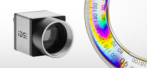
Use of on-camera data pre-processing of IDS polarisation cameras
With the knowledge of polarised light, reflections and highlights can be reduced or contrasts of fine structures increased in industrial image processing. Even physical properties such as material tensions that act below the surface can be visualised. To determine the polarisation information, up to now 4 sequential images with different orientation of the polarisation filter and subsequent PC processing were necessary. With Sony's Polarsens technology, a single recording is all that is needed. Additional data pre-processing converts the raw data in real time from IDS polarisation cameras into useful image formats, for more effective further processing or evaluation in the host PC.
What is the difference between an IDS polarisation camera and a normal camera? What are the possibilities of pre-processing the polarisation information in the camera? In order to understand the application of these special cameras, a short technical excursion is necessary.
We already know that light is electromagnetic waves, which contain all the important information to describe the characteristics of light that are visible to us. Both the human eye and the image sensors of cameras can capture the direction, intensity (amplitude) and color (wavelength) of light and digitise it for image processing. The wavelength range of light is only a small part of the entire spectrum of electromagnetic waves.

Another feature that has so far mainly been used in image processing with special illumination, filter glasses and optics is the polarisation of the waves. Polarisation does not describe the direction of the light beams themselves, but the direction of the wave amplitudes in which the light particles (photons) oscillate perpendicular to the direction of propagation. The waves of unpolarised light oscillate in different directions. Incandescent lamps or sunlight are examples. If the photons move in only one direction, we speak of linearly polarised light. Special polarisers absorb or attenuate incident light that oscillates in all but one plane - its polarisation axis - resulting in an almost linear polarisation.
The behaviour of linear polarisation filters
The influence on the resulting intensity of a light wave with the initial intensity I0 when passing through a linear polarisation filter was already proven in 1808 by the French physicist Étienne Louis Malus and mathematically described with the "Law of Malus": I = I0 * cos²(Φ)
Accordingly, light waves that are twisted in relation to the optical axis of the polariser are not generally blocked, but their intensity is attenuated depending on the angle and polarised in the direction of the filter. The behaviour of linear polarisers is often misleadingly described or represented. Unfortunately, the graphic above is another example of this.
What do reflections have to do with polarisation?
On highly reflective surfaces, such as glass, light rays can be deflected. Depending on the viewing angle of the object, unwanted reflections in the direction of the observer may then occur. The following example with a car shows how car windows become opaque due to such light reflections. Objects or persons in the interior are thus hardly recognisable - become almost "invisible".
If light reflections occur on non-metallic surfaces (as here on glass), physical processes cause a natural polarisation of the light. This means that this special polarised light component and thus the glare effect can be reduced by using an appropriate polarising filter. The unpolarised part of the light can still pass through the filter.
Light reflections on a windshield can be removed by polarising filters


Reflections on metallic surfaces cannot be eliminated by a polarising filter alone! On metallic surfaces the light is not polarised, but only reflected. Therefore, despite the polarising camera, it is absolutely necessary to mount an additional polarising filter on the illumination, depending on the application, in order to suppress disturbing light reflections.
The use of already polarised light (e.g. through a polarising filter foil) further reduces the generation of reflections on surfaces. Special computer displays (without touch function) are therefore provided with an "anti-reflective" film. Although the light intensity decreases with narrow viewing angles, no reflections are created. If you look at these displays almost parallel, the screen seems to be dark!
Importance of polarisation for image processing
For the pure perception or digitalisation of light it makes no technical difference whether we are dealing with polarised or non-polarised light. In digital image processing, it is primarily the illumination of a scene that is essential to make certain features visible. But everyone who has ever taken a picture with lighting knows the advantages and disadvantages. The unwanted shadows are rather easy to control with additional or stronger lighting from different directions. In combination with diffuser screens, a more homogeneous illumination of the scene can be achieved. But in connection with light, one always has to fight with disturbing reflections and fading, which often leaves important features undiscovered. If a mirroring erases information, for example, because a car driver's face is outshined by the reflection on the windshield, this cannot be restored after image acquisition with any image processing technique. Especially in industrial image processing, diffuse scattered light is often used to reduce the disturbing influences as much as possible. Depending on the application, however, optimum lighting can be very expensive.
But not always more is better or more suitable! In the case of light, the essentials can also be made visible through targeted filtering of the disturbing influences. The knowledge about polarised light, how it is generated and how to influence it, provides approaches to solutions. Polarisation filters are used in image processing to reduce reflections or highlights but also to increase contrast. They are also useful in stress analysis to visualise physical properties below the surface.
Advantage polarisation
Since light is polarised not only by superficial but also by other physical properties such as mechanical stress or light refraction, object features and defects can be made visible that cannot be detected by normal image sensors.
Making the invisible visible
Material defects or object features that are sought after do not always become visible through more light or by eliminating disturbing influences. In the following picture example it only seems as if the contents that are important for us are exposed more or their light intensity is increased. That's not so. The light is polarised by the reflections of the light from the stains and scratches.
Using the degree of polarisation, stains and scratches become visible during glass inspection


The fingerprints and scratches can only be seen very clearly here by visualising the "degree of polarisation", which makes the polarised light rays more clearly visible than unpolarised light. But normal camera sensors do not record the polarisation of light. This means that the information is lost during the acquisition. A visualisation or even a subsequent polarisation correction by image processing cannot be applied anymore, as even in a RAW-file it is not recognisable anymore where light was captured with which angle and degree of polarisation.
To calculate such an image it is necessary to capture the polarisation of the light of this scene in numbers. This makes it possible to subsequently process an already digitised image or to make "invisible" features visible to us. This quantisation of the polarisation is very easy to achieve with Sony's Polarsens technology, for example. This means that with cameras such as our GV-5080CP-P (GigE Vision) or U3-3080CP-P (USB3 Vision), which include the Sony IMX250MZR mono Polarsens sensor, polarisation information can be captured in a single image.
IDS camera with 4x linear polariser
IDS polarisation cameras with the Sony IMX250MZR mono polarisation sensor are available as GigE Vision and USB3 Vision versions.
 The technical data sheets
- U3-3080CP-P-GL Rev.2
- GV-5080CP-P-GL
can be downloaded from our website.
A single image is sufficient to capture the polarisation information together with the image content. No special accessories such as a polarised light source or polarising filters are required. This is made possible by the innovative design of the Sony sensor.

The "four-directional polariser" located between photodiodes and micro lenses generates a sensor raw image with four polarisation directions (0°, 45°, 90° or 135°) in one image by the principle of linear polarisation filters. A different intensity is measured for each angle of the polarising filters. Four adjacent pixels in a 2x2 cluster with their four different polarisation filters form a "calculation unit". The real 5 megapixels of the sensor are thus divided into 4 smaller images for one polarisation angle each, but their image content reflects the same moment. This means that the camera has the optimum output data for calculating the polarisation information - and that with every shot.
The four single images are available with 1.26 MP in a reduced resolution and brightness, which can lead to strong noise of the result values during the following polarisation determinations in the border area. Therefore, make sure that you have suitable and sufficient lighting when capturing images.
The mathematical calculation basis for the polarisation state of each sensor calculation unit is the Stokes vector. With the help of its 4 components, the degree of polarisation and angle of polarisation can be determined from the four measured light intensities.

Industrial cameras provide the image material for digital processing. Even though the raw format of an image sensor offers the most possibilities for subsequent image processing, it is not suitable for direct visual inspection, for example. Through preprocessing, important and often needed results could be calculated directly. It also saves time and PC computing load. In combination with Sony Polarsens technology, other useful image formats are therefore available in addition to the sensor raw format, which can provide optimal output data for image processing on the PC.
Starting with camera firmware version 2.4, uEye CP polarisation cameras are capable of independently determining the direction and degree of polarised light from a single image acquisition using the raw image data of the "four-directional polariser" by pixel preprocessing. This allows new image information to be calculated and visualised with the polarisation data, for example to make a contrast visible. With predefined, selectable image components, the user can, for example, filter out disturbing light reflections directly from the sensor raw data or make reflective object features visible in almost complete darkness even before the image is transmitted to the PC - with just one click!
Advantage "oncamera data pre-processing"
- It's so easy - Simplifies the work of the image process engineer, who already receives the optimal data for further processing from the camera.
- Efficient - Saves PC resources. Camera and PC share the work effectively.
- Vision-compliant - Result data from the camera is available to any standard vision application without the need for additional or special software.
Application specific image formats
For the most important applications, 8 image formats are offered for selection, which are calculated in real-time in the camera's FPGA.
Raw
Image format: 8 bit mono, 2448 x 2048 pixels (full sensor resolution)
In raw mode, the camera delivers the sensor data without preprocessing in full 5 MPixel resolution as an 8-bit grayscale image. With the intensity values of the differently polarised pixel filters, both angle and degree of polarisation of the linearly polarised light can be determined. The raw data format is thus the basis for own PC-based evaluations and calculations in the customer application.
Intensity
Image format: 8 bit mono, 1216 x 1024 pixels (1/4 of the sensor resolution)
"Intensity" corresponds to the average value (m) of the four measured light intensities after passing through the "four-directional polariser" with the four polarisation directions 0°, 45°, 90° or 135°. It is calculated with m = (I_0° + I_45° + I_90° + I_135°) / 4
The image format represents the brightness without polarisation information of light. It is therefore most comparable to the intensity value that a normal mono image sensor would capture.
IntensityNonPolarized
Image format: 8 bit mono, 1216 x 1024 pixels (1/4 of the sensor resolution)
This intensity value (I_min) only corresponds to the proportion of unpolarised light in the image. The polarised part of the light is calculated with I_min = m * (1 - DoP). With this image format, light reflections are already effectively reduced.
IntensityOnlyPolarized
Image format: 8 bit mono, 1216 x 1024 pixels (1/4 of the sensor resolution)
This grey-value image (I_amp) contains only the polarised part of the light. It is calculated using I_amp = I_max - I_min. Areas in which no polarised light is present become darker. The current brightness of the individual pixels is fully integrated into the image. Exposure changes affect the display. This distinguishes the mode from the polarisation degree (DoP) mode, because here the absolute values and not the relative portions are output.
DegreeOfPolarization (DoP)
Image format: 8 bit mono, 1216 x 1024 pixels (1/4 of the sensor resolution)
The degree of polarisation indicates the percentage of polarised light in relation to the total intensity. Due to the relative values, the DoP calculation is only slightly affected by exposure changes as long as no clipping occurs.
- The higher the degree of polarisation, the better the angles determined are suitable for subsequent calculations and analyses.
- If the DoP values are too low, the polarisation information becomes useless for analysis. There is a lot of noise in the image information.
In applications with polarised light DoP is an important value for the quality of the results or a good measure for the qualification of the right lighting conditions of a scene.
PolarizationAngle
Image format: 8 bit mono, 1216 x 1024 pixels (1/4 of the sensor resolution)
This image mode displays all calculated polarisation angles (1 angle per "four-directional polariser" with 2x2 pixels) as a gray scale image. The angles are scaled internally so that they are output in the range 0-180°. Negative output values therefore do not occur.
In areas with very little polarised light, the angular results vary greatly, since the angular information from the "four-directional polarisers" cannot be extracted cleanly by noise. This often means that a stable angle calculation is not possible.
When using the calculated polarisation angles in an application, prior qualification by the degree of polarisation (DoP) is recommended.
Combination of angle and polarisation degree information
Using the HSV color space, the camera can produce a combination image format with more than one piece of information. By linking, for example, the angle and degree of polarisation in an image, the results can be interpreted particularly well. This also results in a false-color display, which also visualises the relationships.
Especially if the angle information cannot be extracted cleanly by noise, because very little polarised light is available, the results are mostly useless for meaningful further processing. In this case, a combination format provides a measure for validation in the same image in addition to the angle value!
IDSHeatMap
Image format: 24 bit RGB, 1216 x 1024 pixels (1/4 of the sensor resolution), HSV-based (H = angle, V = DoP, S = 100%)
In this combination format, the determined angle of polarisation is combined with the degree of polarisation. The brightness of the resulting image is scaled by the DoP. As a result, dark areas show that the angle information is not reliable because the polarisation component is very low and the angle calculation can therefore be inaccurate. For bright areas, on the other hand, there is a very large polarisation component and the angle can be reliably determined.

IDSColorMap
Image format: 24 bit RGB, 1216 x 1024 pixels (1/4 of the sensor resolution), HSV-based (H = angle, V = abs (mono - DoP), S = DoP)
In this combination format, the determined angle of polarisation is also linked to the degree of polarisation. However, here the actual gray value image is included in the calculation. The brightness here corresponds to the amount of the difference between the grayscale image and DoP. This makes the image brighter overall due to bright mono image areas as well as high DoP. Only areas where there is neither brightness information nor high DoP information become dark or black. Additionally DoP is used as saturation. Thus, strong colors indicate a high proportion of polarised light in the image area.

Configuration via the Vision Cockpit
The image formats of IDS polarisation cameras can be set and used with any GenICam-compatible software. We explain the configuration of the camera parameters with the help of the Vision Cockpit, which you can install with our software development kit IDS peak. The image formats can be found as individually selectable image components in the ImageFormatControl node. If you have opened your camera with firmware 2.4, you can find the settings by entering for example "Component" in the search field.
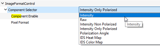
You activate the individual image formats with the Vision Cockpit as follows:
- Disable image acquisition
- select the desired image format with the "Component Selector
- Activate image format with "Component Enable
- Restart image acquisition
The camera automatically switches to the required image format (e.g. "8 Bit Mono" or "24 Bit RGB").
Programming with IDS peak
To use the new image formats in your own application only a few lines of source code are necessary. The following source code blocks show the programming of the image formats with IDS peak in the programming language C#.
Retrieving all available image components
var imageComponentsNode = nodeMapRemoteDevice.FindNode<peak.core.nodes.EnumerationNode>("ComponentSelector");
var availableImageComponents = imageComponentsNode.Entries();
foreach (var entry in availableImageComponents)
{
    display(entry.StringValue());
}
Querying the currently active image component
var activeImageComponent = "";
foreach (var entry in availableImageComponents)
{
    imageComponentsNode.SetCurrentEntry(entry);
    if (nodeMapRemoteDevice.FindNode<peak.core.nodes.BooleanNode>("ComponentEnable").Value() == true)
    {
       activeImageComponent = entry.StringValue();
    }
}
display(activeImageComponent);
Select and activate an image component
imageComponentsNode.SetCurrentEntry("IDSHeatMap");
nodeMapRemoteDevice.FindNode<peak.core.nodes.BooleanNode>("ComponentEnable").SetValue(true);
Summary
Polarisation is a property of light that enables the recognition of object attributes that are invisible to the human eye and also "normal" image sensors. This makes it an important tool for digital image processing in applications with reflective or translucent surfaces. With the SONY IMX250MZR sensor and the oncamera pixel pre-processing, IDS polarisation cameras are able to determine all necessary polarisation information of the image scene with a single image acquisition and to provide this information in different pixel formats to the host PC for further processing or direct evaluation.
FPGA-accelerated algorithms make cameras more than suppliers of pure sensor data. In real time, they already provide meaningful evaluations that can be further used by any GenICam-compliant application via GigE or USB3 vision interface. IDS polarisation cameras thus become part of the image processing and reduce the computing load of the host PC.
Test for yourself how easy it is to make object attributes visible with just one click before the image is transferred to the PC.

Dipl.-Ing. Heiko Seitz is working at IDS since 2001. After years as a developer in the field of camera software, he now supports technological communication at IDS as Product Marketing Manager. With his experience, he bridges the gap between complex technology and practical knowledge transfer – for example in technical articles, webinars, or lectures.
Vision Channel
Videos and live sessions about machine vision.
Your project
How can we support you in your project? Together we will find the right solution for you!
Newsletter
Stay up to date and subscribe to our newsletter.